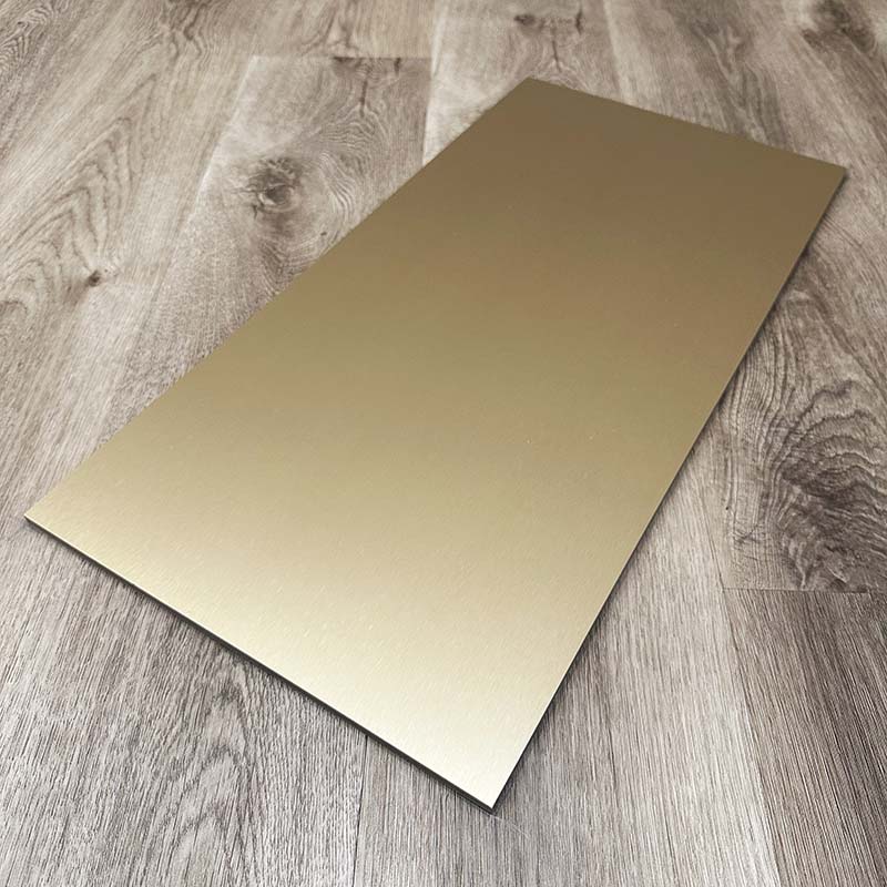
Upgrading a room's aesthetic brings immense satisfaction. Modern, durable wall finishes elevate interior spaces beautifully. Yet, the moment you encounter an electrical outlet, the renovation often hits a stressful roadblock. The rigid nature of a carbon crystal panel makes it incredibly durable but tricky to manipulate. Poor measurements or improper cutting methods easily ruin your boards. You might face chipped finishes, wasted materials, or electrical setups failing to meet fire safety codes. Relying on guesswork turns a straightforward upgrade into a costly disaster.
This guide provides a standardized, low-risk framework for tackling these exact obstacles. You will learn the best ways to measure, cut, and fit panels around existing switches. We outline precise tooling requirements and transfer techniques. Following these methods ensures your final installation remains structurally sound and visually flawless.
Key Takeaways
Safety First: Electrical code compliance requires power isolation and the use of electrical box extenders to account for the panel's added depth.
Precision Tooling: Standard wood blades cause chipping; high-tooth-count or oscillating blades are required to protect the delicate surface film of carbon crystal panels.
Waste Mitigation: Utilizing transfer methods (e.g., chalk marking) or rigid templates drastically reduces the risk of measuring errors and subsequent material loss.
Stress Relief: Drilling pilot holes in cutout corners prevents micro-cracks from propagating through the carbon crystal core.
1. Project Framing and Electrical Safety Compliance
Isolating the Infrastructure
Electrical safety represents the foundational step of any wall cladding project. You must isolate the power infrastructure before a single measurement occurs. Locate your main breaker panel. Turn off the circuit supplying power to the specific room or wall. You cannot rely solely on the switch position to guarantee safety. Always verify zero voltage at the receptacle. Use a reliable non-contact voltage tester. Wave the tester near the outlet slots and wiring terminals. If it beeps or flashes, power remains active. Find the correct breaker before proceeding.
Evaluating Depth Requirements
You must assess the thickness of your new wall material. Typically, these boards measure between 5mm and 8mm thick. This added depth changes the spatial relationship between the electrical box and the finished wall surface. Once you install the boards, the original electrical box will sit recessed inside the wall cavity. You cannot simply screw the faceplate over this recessed gap. Doing so pulls the receptacle loose or bends the internal mounting yoke.
Code Compliance (Fire Safety)
Electrical codes mandate specific safety standards regarding recessed receptacles. Industry frameworks, such as the National Electrical Code, require the use of electrical box extenders. Professionals often call these spark rings. An extender acts as a sleeve. It bridges the gap between the old box and the new wall surface. This prevents combustible dust or debris from settling in the void. It ensures the receptacle sits entirely flush. Overlooking this step creates severe fire hazards.
Removal of Existing Hardware
Safe removal of existing hardware prevents accidental damage to both the wall and the wiring. Follow a structured teardown process before measuring.
Unscrew the decorative faceplate and set it aside in a secure container.
Remove the top and bottom mounting screws holding the receptacle to the electrical box.
Gently pull the switch or outlet forward, extending the wires out of the box.
Wrap the side terminals in electrical tape to insulate the exposed connection points.
Tuck the wires and receptacle gently back into the box to clear the perimeter for accurate measuring.
2. Evaluating Measurement Strategies to Mitigate Material Waste
The Tape Measure Approach (X/Y Axis Method)
The traditional tape measure approach relies on an X/Y coordinate system. You measure from a known level point, such as an adjacent installed board or the baseboard. You determine the distance to the bottom, top, left, and right edges of the electrical box. You then transfer these exact coordinates to the back of your new material. The risk profile here remains exceptionally high. Human error thrives in this process. Reversing dimensions or misreading the tape leads directly to ruined panels.
The Direct Transfer Method (Chalk/Lipstick Hack)
Contractors often use the direct transfer method for exact placement. This technique dramatically reduces measurement errors. You apply a highly visible, easily wipeable pigment to the front edges of the electrical box. Chalk powder, washable markers, or even bright lipstick work perfectly. Next, you dry-fit the board into its final position. Press it firmly against the pigmented box. The pigment leaves an exact imprint on the back of the material. This method is highly reliable. However, you must ensure the board is perfectly plumb before pressing it against the wall.
Template Creation
Template creation serves as an insurance policy for complex cuts. You use rigid cardboard or scrap material to mimic the final board. You cut your outlet holes into this cheap material first. Once you verify the scrap template fits perfectly over the switches, you trace its exact dimensions onto the expensive material. We highly recommend this approach for irregular obstacles. It proves invaluable when dealing with multi-gang switch boxes where tolerances remain extremely tight.
Measurement Strategy
Complexity Level
Risk of Material Waste
Best Use Case
Tape Measure (X/Y)
Moderate
High
Single outlets on entirely flat, empty walls.
Direct Transfer
Low
Low
Standard installations requiring fast, accurate single-box cuts.
Template Creation
High
Very Low
Multiple adjacent switches, angled walls, or irregular obstacles.
3. Tooling Selection for Carbon Crystal and Metal Textures
Material Realities
Understanding the material composition dictates your tooling choices. These boards feature an incredibly rigid base layer covered by a decorative top film. Using standard, aggressive wood blades causes immediate delamination. The aggressive teeth rip the top film away from the core. This damage becomes especially prominent on specialized finishes. A Metal Texture Carbon Crystal Wall Panel requires utmost care. The metallic visual film splinters if subjected to intense vibration or blunt-force cutting tools.
Oscillating Multi-Tools
Oscillating multi-tools offer the most precise control for plunge cuts. They operate via rapid side-to-side vibration rather than a spinning or reciprocating motion. This allows for a clean entry without stressing the surrounding surface. Evaluate your blade types carefully. A fine-tooth bimetal blade works best. It slices through the rigid core smoothly. Avoid coarse wood blades. They generate too much friction and easily snag the decorative film layer.
Jigsaws and Blade Selection
Many installers prefer jigsaws for cutting panels before placing them on the wall. If you choose a jigsaw, you must mandate specific settings. Turn the orbital action completely off. Orbital action forces the blade forward and backward, which aggressively tears composite materials. Select a metal-cutting blade or a laminate-cutting blade. These blades feature a high tooth-per-inch (TPI) count. More teeth mean a smoother, slower, and safer cut through the rigid substrate.
Surface Protection
The shoe of a jigsaw easily scratches premium finishes as it glides across the surface. You must implement surface protection protocols. Follow these best practices to maintain a pristine aesthetic:
Always attempt to cut from the back of the board whenever feasible.
If you must cut from the front, apply wide painters tape directly over the cut line.
Draw your final measurement marks on top of the painters tape.
Wipe the metal shoe of your saw clean before resting it on the material.
4. Execution: The Low-Risk Cutting Framework
Marking and Verification
Preparation dictates success. Double-check all transferred dimensions against the physical electrical box. Take a moment to verify your layout before any destructive action occurs. Hold a tape measure against the drawn rectangle and compare it to the wall receptacle. Precision at this stage prevents costly replacements later. You only get one chance to penetrate a premium Carbon Crystal Panel.
Drilling Pilot Holes (Stress Relief)
Cutting sharp ninety-degree corners introduces structural stress into the material. The blade easily binds in a tight corner. When the blade binds, it transfers violent kinetic energy into the core, causing micro-fractures. You prevent this by drilling pilot holes. Grab a drill bit slightly larger than your saw blade. Drill one hole in each of the four corners of your marked rectangle. These holes provide stress relief. They allow you to turn the saw blade smoothly without fighting the rigid material.
Executing the Cut
Begin cutting by dropping your blade into one of the pre-drilled corner holes. Maintain a steady, remarkably slow feed rate. Let the tool do the actual work. Forcing the blade forward causes friction burns on the core material. It also shatters the delicate edges of the top film. Move carefully from corner to corner. Support the cutout section from underneath as you finish the final line. Allowing the center piece to snap off under its own weight will peel the surrounding decorative film.
Tolerance Considerations
You do not need an absolutely airtight fit around the electrical box. Attempting a zero-clearance cut usually results in frustration. Cut the hole approximately 1/8-inch to 1/4-inch larger than the box itself. This intentional gap allows for structural expansion. Building materials shift slightly over time due to temperature changes. The minor alignment gap provides necessary breathing room. Furthermore, a standard electrical faceplate easily conceals a 1/4-inch gap, ensuring a visually flawless finish.
5. Final Alignment and Shortlisting Next Steps
Dry-Fitting
Never apply construction adhesive before testing the fit. Lift the freshly cut board and press it into place on the wall. Verify the exact clearance around the receptacle. The box should sit comfortably inside the cutout without binding against the edges. Check your vertical seams and ensure the board aligns perfectly with adjacent panels. If the hole feels too tight, take the board down. Use a file or sandpaper block to gently widen the opening.
Applying Adhesive and Securing
Once you confirm a perfect fit, place the board face down on a protected surface. Distribute structural adhesive evenly across the back. Use a zigzag pattern for optimal coverage. However, you must avoid the immediate perimeter of the electrical cutout. Keep the adhesive at least two inches away from the hole. You do not want wet adhesive squeezing out into the electrical box and coating the sensitive wiring. Press the board firmly onto the wall.
Reassembling the Receptacle
Your wall cladding is now secure. It is time to reassemble the electrical components. Slide your electrical box extender over the internal box. Gently pull the outlet receptacle through the new extender ring. Ensure the wires remain securely attached to the terminals. Drive longer mounting screws through the receptacle, through the extender, and into the original box. Secure it tightly so the metal yoke sits entirely flush against the new wall surface. Finally, attach the decorative faceplate.
Quality Assurance
A rigorous quality check completes the installation. Follow these final verification steps:
Inspect the perimeter of the faceplate for any visible wall gaps.
Ensure the faceplate sits completely flat without bowing or warping.
Verify the switches or outlet plugs operate smoothly without catching on the cover.
Return to your breaker box and restore mains power to the room.
Plug in an electrical tester or a simple lamp to confirm full electrical functionality.
Conclusion
Integrating modern wall panels around existing electrical infrastructure demands patience and exactness. You must prioritize safety by thoroughly isolating power and utilizing proper box extenders. Deploying foolproof measurement techniques, like the direct transfer method, eliminates guesswork. Furthermore, selecting fine-tooth tooling protects the delicate surface film from devastating micro-cracks and delamination.
Always remember that precision during the evaluation stage remains far cheaper than replacing a ruined board. Take your time, drill your pilot holes, and never force a saw blade through rigid materials. Before you begin your next renovation project, review the manufacturer-specific cutting guidelines for your chosen product series. Proper preparation guarantees a stunning, durable, and code-compliant finish.
FAQ
Q: Can I cut a carbon crystal panel with a standard utility knife?
A: No. Unlike thin PVC or soft wallcoverings, carbon crystal panels are rigid and require power tools with fine-tooth blades for clean penetration.
Q: What happens if I cut the hole slightly too large?
A: Oversized switch plates (jumbo plates) can be purchased to cover gaps up to 3/8 of an inch, salvaging panels with minor cutting inaccuracies.
Q: Is it safe to install metal texture carbon crystal wall panels near outlets?
A: Yes, provided the panel material is inherently non-conductive (the metal texture is usually a visual film layer) and electrical box extenders are correctly utilized to isolate the wiring. Verify specific product conductivity with the manufacturer.
The company was established in 2018 and specializes in new environmentally friendly indoor decorative materials such as SPC flooring, WPC flooring, carbon crystal flooring, wood veneer panels, and carbon crystal wall panels.